Thursday, June 4, 2009

Creating a simple mesh - PN diode

This post show how to create a very simple mesh for a PN diode, realized with a p Gaussian diffusion on an n substrate. In this example we are more concerned with illustrating the need for a correct mesh, rather than presenting a realistic simulation.

The mesh file is largely based on the example/PN_diode mesh from GSS.

diode_mesh.inp

MESH Type=GSS ModelFile=mb_pn.cgns Triangle="pzA"
XMESH WIDTH=3.0 X.MIN=-3 X.MAX=0 N.SPACES=10
XMESH WIDTH=3.0 X.MIN=0 X.MAX=3 N.SPACES=60

YMESH DEPTH=3.0 N.SPACES=30

# Region and electrode statements
REGION Label=Si Material=Si
SEGMENT Label=Anode Location=TOP X.MIN=-1 X.MAX=1.0
SEGMENT Label=Cathode Location=BOTTOM
SEGMENT Label=Probe Direction=Vertical X=0.5 Y.top=-0.1 Y.bottom=-2

# Specify impurity profiles
PROFILE Type=Uniform Ion=Donor N.PEAK=1E15 X.MIN=-3 X.MAX=3.0 \
Y.TOP=0.0 Y.BOTTOM=-3.0
PROFILE Type=Gauss Ion=Acceptor N.PEAK=1E19 X.MIN=-1 X.MAX=1.0 \
Y.TOP=0.0 Y.BOTTOM=0.0 X.CHAR=0.3 Y.JUNCTION=-0.5
set Carrier = pn # specify carrier type
set LatticeTemp = 3e2 # specify initial temperature of device at 300K.
set DopingScale = 1e18

boundary Type = OhmicContact ID=Anode Res=0 Cap=0 Ind=0
boundary Type = OhmicContact ID=Cathode Res=0 Cap=0 Ind=0

EXPORT CoreFile=mb_pn_coarse.cgns AscFile=mb_pn_coarse.tif VTKFile=mb_pn_coarse.vtk

REFINE Variable=Doping Measure=SignedLog Dispersion=3
METHOD Type=DDML1 Scheme=Newton NS=LineSearch LS=GMRES SOLVE Type=EQUILIBRIUM #compute equilibrium state
REFINE Variable=Potential Measure=Linear Dispersion=0.1
SOLVE Type=EQUILIBRIUM
EXPORT CoreFile=mb_pn.cgns AscFile=mb_pn.tif VTKFile=mb_pn.vtk
END

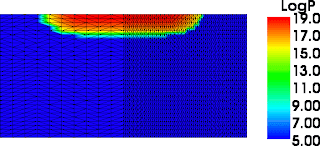
This is how the mb_pn_coarse.vtk mesh looks like. The difference in mesh refinement in the left and right side is intentional to show the effects of improper meshing.


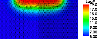
This is how the mb_pn.vtk mesh looks like. Please note how the junction has been refined on the left and right side.


Then we can take both meshes and turn on the diode, bringing the potential of the p contact up to 0.8 V. The computed currents are 3.889297e-02 mA for the coarse mesh and 3.876786e-02 for the fine mesh.

Monday, June 1, 2009

Installation - Part 2

Step 2: Compiling everything:

2.a) Petsc
type these in the terminal. It seems that the new gcc compiler has some issue with the gss code.

export CC=/usr/bin/gcc-4.2
export CXX=/usr/bin/g++-4.2


gunzip petsc
tar -xvf petsc
cd petsc
export PETSC_DIR=`pwd`

./config/configure.py --with-cc=gcc --download-mpich=1 --with-clanguage=cxx --with-mpi=0 --download-c-blas-lapack=1 --with-precision=longdouble --with-shared=0


2.b) Cgnslib
bunzip2 cgnslib
tar -xvf cgnslib
cd cgsnslib
./configure
make
sudo make install

2.c) GSS
gunzip the file
tar -xvf the file
cd GSS_dev
export GSS_DIR=`pwd`
./configure
make
sudo make install

It takes a while but eventually you should have a working TCAD simulator.
Please let me know if you encounter any problem.

Installation - Part 1

Step 1: Download all the files

Download all the necessary files in the same compile directory:
1) go to the GSS download page and get the gss and the ngspice archives.
The ones I used are named: gss-tcad-0.46-p11.tar.gz and cogenda-ngspice-gss-0.46-p11.tar.gz

2) Download the PETSC library: petsc-2.3.3. I used version 8 for better compatibility. Download the ls.c patch from the gss website.

3) Download cgnslib-2.5.1

4) Install the following software with synaptic. Open a terminal and paste

sudo apt-get bison libtiff4 libtiff4-dev flex-old gcc gfortran libblas3gf liblapack3gf tk tk-dev tcl-dev vtk-tcl libadolc0 make makedev

After you enter the password the package should install automatically.
If I forgot a package please tell me.

Where do I start?

Good question. A good general resource is TCAD Central where you can find an exhaustive collection of news, conferences, and software.
But ultimately, if you want to learn about TCAD you need to run some simulations yourself. I recommend the GSS simulator by Gong Ding. It is powerful, free, open source, and its synthax is based on Medici, a popular TCAD software.
Installation was not trivial, so I am going to provide a step by step guide soon.

Step 0: Install linux
Install linux. Honestly, it's worth it. Major TCAD software runs on linux anyways.
Plus there are lots of open source post-processing tools that help to interpret and analyze simulations. And installing linux is much less painful these days with stuff like Wubi and such...
If you want advice, I personally use Ubuntu 8 and it works pretty well.

What is TCAD, anyway?

TCAD stands for Technology Computer Aided Design, which is not that self-explanatory. What it really refers to is computer programs able to simulate either the workings of a semiconductor device (device simulation) or the fabrication process of a semiconductor device (process simulation).
Often the result of a process simulation, which is called a "mesh" or "grid" is fed into a device simulator to evaluate the performance or the behavior of the device that has been "virtually fabricated".
Simulations are very inexpensive and fast compared to actual prototype fabrication. They are also an excellent tool to understand semiconductor physics.
 
# tracking